
Like most Nissan motors, the CA18DET has a maze of vacuum lines that quickly become confusing to those unfamiliar with the motor. The following is a quick guide of what needs to be hooked up and where in order to get your CA18DET up running.
Upper Intake Manifold (rear)

Read below for the explanations and click here for a larger view.
- Connects to the passenger side valve cover at the front of the motor.
- To the brake booster (vacuum line that comes from behind the master cylinder assembly)
- Small vacuum nipple that should be t’ed to the fuel pressure regulator and the lower manifold butterfly assembly (located behind the fpr). A boost gauge can also be t’ed to this line. **
- Water outlet that goes to turbo side of motor to liquid cool the turbo Line after turbo goes to water inlet on turbo side of block.
- Water inlet from positive flow from water pump that feeds #4.
- The vacuum nipple just behind the throttle body is either capped or used for vacuum source on blow off valve.
The area circled in blue in the above picture is where three hard vacuum lines are on the stock manifold. This assembly is not necessary and should be removed.
** Note: The signal for the wastegate can be t’ed into #3 but it is recommended to run the wategate line as close as possible to the turbo so that boost leaks will not cause the turbo to overboost.
Throttle Body

Fullsize image here.
- Water outlet to small nipple on water bracket located under upper manifold. (water bracket pictured below) **
- Vacuum/boost nipple before throttle plate is capped. Will cause boost leak if left open.
- Water inlet from cylinder head water t. (water t pictured below) **
** Note: #1 and #3 can be bypassed by running a water line directly from the cylinder head water t to the nipple on the water bracket that serves as the inlet for #1 above.
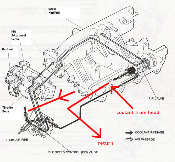
Idle Control
")
Fullsize image here.
- The is the F.I.C.D. valve and bumps the idle up when the Air Conditioner is turned on. If you don’t have AC, you don’t have to plug it in. (Not pictured but on the other side of this unit is the idle adjustment screw. The CA18DET should idle right at 850 rpm when warm)
- #2 and #3 are called the I.A.A. (Idle Air Adjusment) and this is the air feed for this unit. It connects to the intercooler piping before your throttle body.
- The A.A.C. valve receives a signal from the e.c.u. and makes idle adjustments on the fly.
- My manifold is modified but the stock manifold has a hard line coming out of this hole that connects to the top of the air regulator (#5)
- The air regulator allows extra air into the manifold on cold start. The top of the regulator connects to #4 and the bottom line is t’ed to #2.
Air Regulator and Water T Clarified

Fullsize image here.
- Outlet for the air regulator and connects to #4 of the idle control section.
- Inlet for the air regulator and t’s into #2 from the idle control section.
- Small water outlet on the cylinder head water t. Connects to the inlet of the throttle body. #3 from throttle body section.
- Water outlet that connects to the lower water bracket. (see next section)
Lower Water Bracket

The lower water bracket from the ca18det mount on the underside of the upper intake manifold. (Fullsize)
- Water outlet that connects to the heater core. If you don’t have heat and have removed the heater core, this will connect directly to the the water inlet on the block.
- Outlet for liquid colling the turbo. Connects to #5 from upper intake manifold (rear) section.
- Water inlet from throttle body water lines. #1 from throttle body section.
- Water inlet from cylinder head water t. #4 from air regulator and water t clarified section.
- Water inlet from t on lower radiator hose.
Oil Return and Water Inlet

Fullsize image here.
- Oil return from valve cover, connects to #2.
- Oil returb from valve cover, connects to #1.
- Oil return from valve cover, connects to #4.
- Oil return from valve cover, connects to #3.
- Water return from heater core. If heater core is not present, connects to #1 from lower water bracket section.
Turbo Side Water and Oil

Fullsize image here.
- (not pictured) oil fitting to block connects to top of turbo.
- Oil drain from bottom of turbo connects to large nipple on side of oil pan.
- Water return from turbo to block. (mine is blocked as I do not water cool my turbo)
- Valve cover vent. Connects to intake manifold in stock application. It is recommended to vent the valve cover to an oil catch can and block the inlet on the intake.
