
 install.")
Recently project S2000 has enjoyed the addition of a Comptech supercharger to give it a little more … ooomph. But even with the stage 1 pulley peaking at a paltry 5psi, it became clear rather early that the Comptech system is very prone to heat soak. Being daily driven in Tennessee means that this car needs to handle summer temps that touch 100 degrees F. With this year’s mild winter already causing hints of heat soak on warmer days, an intercooler is a must on project S2000 to prevent this minor annoyance from becoming something much worse as the summer months approach.
Intercooling on a Comptech supercharger usually comes in the form of the Power Cooler. The Power Cooler (a.k.a. aftercooler) is basically a liquid-to-air intercooler. It comes with an electric water pump, front heat exchanger, intercooler core and all associated lines. However, without getting into the merits of liquid-to-air vs air-to-air intercooling, I will say that for project S2000, a FMIC (front mount intercooler) was chosen as the means to cool the intake charge. The FMIC route was chosen in this case to avoid the inherit complexity of the Power Cooler and to allow an easy transition to turbo power if it is desired in the future.
So for this install, a FMIC kit was purchased from Ultimate-Racing.com in Canada. Not only did they have a very reasonable price but they also have dyno results that highlight the extra cooling capacity that their FMIC offers over the Power Cooler.
The Kit
The Ultimate-Racing kit comes with a large FMIC as well as prefabbed cold and hot pipes. Also, the cold pipe will come with your choice of BOV (blow off valve) flange and for this kit, the HKS SSQV flange was chosen. Refer to the following image for a parts breakdown.

Pictured above: upper hot pipe (1), lower hot pipe (2), lower cold pipe (3) and upper cold pipe (4). Note the SSQV BOV flange on pipe (4).
The Install
During this install you will need to remove the front bumper and some of the underside trim. This process is infinitely easier with the front of the car lifted so first, raise the front of the car by using a lift or ramps.
Placing the car on ramps is a safe and easy way to gain additional access to the front underside. Once parked, make sure to leave the car in 1st gear and engage the parking break to ensure that the car cannot roll backwards.
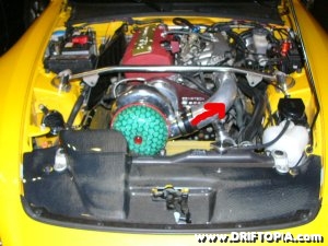
Next, open the hood and go ahead and remove the existing charge pipe from the supercharger and the shroud from the radiator.

The S2000 engine bay before removing the radiator shroud, trim and charge pipe.

The engine bay with the shroud and charge pipe removed.
With the top of the car prepped, proceed to the bottom and begin to remove the bolts and pop rivets that hold the wheel well trim to the front bumper. Once loose, tuck the front of the trim on the outside of the bumper. Move to the center skid / duct plate and work your way along the perimeter of the piece, removing any connections as you go. Once all of the bolts and rivets are removed the piece will fall out.

1 is the center skid plate / air duct and 2 is the front edge of the passenger’s side wheel well trim.

With the underside tray removed, you will now have access to the inside of the front bumper.
To remove the front bumper, you will need to locate and remove several sets of 10mm bolts from throughout the perimeter of the bumper. The following pictures will help locate the bolts but as a general guideline, if the bumper is not pulling away easily from the car, it is still connected somewhere. Also, when pulling the bumper away from the car, take car not to let the edges hit the quarter panels as these panels will scratch each other easily.

These sets of bolts need to be removed from both the driver’s and passenger’s side. Note that the top set is easy accessed by pulling back the wheel well trim that was loosened previously.

Another bolt in the same area that must be removed.

The last bolts are accessed from the top. (Not pictured but near the arrows)

The front bumper removed. Now on to the fun stuff.
Locate the bracket that holds the AC condenser (near the center of the radiator) and unscrew the condenser from the bracket. Remove the 2 bolts that hold the bracket in place and then place the bracket in a clamp or on a hard surface. The mounting portion of the bracket needs to be flipped upside down and then flattened. You can use a vise or clamp to flatten the piece or whack it with a mallet a few times. Either way, once the piece is flattened, reinstall the bracket and the condenser and the assembly will now sit closer to the radiator. (Note: Without modification to the bracket, the condenser will hit the intercooler once it is mounted. Make note of the pictures below as additional lines may or may not need to be adjusted.)

Loosen the condenser from the bracket by removing the screw (opposite side) and then remove the two bolts (circled) and place the bracket on the floor.

The condenser bracket. (before)

The condenser bracket. (after) As you can tell, I used a mallet to flatten it.

The bracket is then reinstalled keeping its reversed position. Notice how the screw that holds the condenser in place now faces forward.
After the bracket is reinstalled, go ahead and install the intercooler core to the frame rail. Looking up from the underside, there will be a small hole at the end of each frame rail that is located between two larger ones. Line the two tabs on the intercooler up with the two holes on the frame rails and secure the intercooler with the supplied hardware.

The mounting point (circled) for the FMIC is located at the end of each frame rail.

With the supplied hardware, secure the intercooler between the frame rails.

This line (foreground) was carefully bent toward the condenser to allow additional clearance for the intercooler. You may or may not have to do this.
With the intercooler in place, install the lower hot pipe (passenger’s side) and pass it into the engine bay as pictured below. The point where the skid plate (the one still attached) connects to the frame rail will need to be trimmed on each side. (a pair of shears will work just fine for this) Once the lower hot pipe is in place, repeat this process for the cold side (driver’s side) and snake the lower pipe around the cold start mechanism. (Note: There is not a connection on the new cold pipe to attach the long intake line that runs between the factory intake and the cold start mechanism. We simply removed the line and the car runs just fine.)

This piece on each side will need to be cut (along dotted line) in order to feed the lower pipes into the engine bay.

Once cut you can see where the lower pipe will pass through and connect with the upper one.


Remove this line (circled) as there is no attachment on the new cold pipe.
Now for the upper pipes. Although it is obvious where these pipes go, I want to make note of one thing. If you remember from the supercharger install, a used kit was installed on the s2000. It appears the supercharger itself had been clocked (compressor housing rotated) as the upper hot pipe would not line up with the lower one. Regardless, the outlet of the supercharger should be horizontal with the cross member just below it. If, like with the used kit, the outlet points upwards, clock the housing to the horizontal by loosening the 8 bolts from the back of the housing and rotating the outlet. Once the outlet is horizontal, tighten the 8 bolts to lock the housing in place.
Also, you will need to install the BOV on the upper cold side pipe before installing. Project S2000 uses a SSQV BOV from HKS. The SSQV offers excellent response but is a P.I.T.A. to install the first few times you work with it. To install the SSQV, you will need to first install the gasket into the flange and then remove the BOV cover. Afterwards, insert the base of the BOV into the flange, slide the compression ring around the base and then with a pair of needle nose pliers, compress the ring and push down on the back side with a flathead screwdriver. The ring will pop into place once it is compressed enough. Finally, hook the vacuum nipple on the back of the BOV to a boost / vacuum reference from the intake manifold. If you need aditional help with the BOV, refer to the SSQV BOV Install on the 240SX.
As noted, the supercharger on the S2000 has been clocked.

This image shows the compressor housing removed from the supercharger. There are 8 bolts around the back perimeter of the housing that secure it to the supercharger. (Note: You don’t have to remove the housing, simply loosening and rotating the housing works fine.)

Once clocked, the outlet of the supercharger will be horizontal with the cross member. Also not ehte installed SSQV BOV.
Before finishing up, check all of the intercooler couplings and make sure that everything is tight. Then cut the front, center skid plate on the edges to allow room for the lower intercooler pipes. (see pics below) Finally, reinstall all of the skid and splash guards as well as the front bumper and trim. And with that, the installation of the FMIC is now complete.

The center skid plate was trimmed on each side to make room for the hot and cold pipes.

Interior pic of the FMIC upper pipes.

This definitely changes the car’s intentions, doesn’t it?
Driving Impressions
This kit works and it works well. After spirited driving, the cold pipe is just that, cold to the touch and heat soak is non-existent. Not only that but this kit has given project S2000 a lot of room to grow. Now of course with any front mount there is going to be a little bit of pressure drop and as such, the boost gauge nows falls shy of 5psi by maxing at 4.5psi. Ironically, the car actually feels a lot smoother and I dare say faster, even with this slight pressure drop. The power curve is less peaky and comes on in a much more linear fashion. We will really see how this kit performs once the 10lb pulley is installed.