Depending on how you count it, the ca18det has over 10 coolant lines. For those building their cars for race use, this can be reduced to only one line (excluding the radiator inlet and outlet). I will demonstrate this with my own car, the ca18det swapped 240sx.

In this tutorial, these 11 coolant connections will be reduced to the radiator inlet and outlet and then one coolant line to the rear of the block.
Note: My car runs a non-liquid cooled turbo and I have removed the heater core. Anyone wishing to keep either one of these systems will be able to modify this how to using additional t’s to route the coolant towards the desired auxiliary systems.
First I will explain the flow path of the ca18det’s coolant. The coolant system has two states, thermostat closed and thermostat opened. With the thermostat closed, the coolant in the block is circulated through the block until the motor is warmed up. In this state the coolant is forced through the outlet on the intake manifold by the water pump where it takes two paths. The majority of the coolant goes directly to the metal conduit below the intake manifold while a small portion is routed through the throttle body before merging with the rest of the coolant in the metal conduit. From this conduit the coolant is then directed either towards the heater core or to the rear of the intake manifold. The coolant that exits the heater core is routed into the intake side of the block while coolant that enters the rear of the manifold crosses the rear of the motor and enters the factory t25 turbo for liquid cooling. The coolant that enters the turbo exits the turbo and enters the block on the exhaust side. When the thermostat opens, fresh coolant (colder) is sucked into the block from the lower radiator hose while hot coolant flows into the radiator from the upper hose. In this manner, fresh (cooler) coolant is introduced into the block once the thermostat opens.
The images below highlight the coolant path.

This image shows the coolant path of the major components on the ca18det. Coolant flows into the block from the lower radiator hose (when the thermostat is opened). Coolant enters the radiator through the upper hose (when the thermostat is opened). 1a is where coolant always exits the block and eventually reaches 3a, the block inlet.

This tutorial removes virtually all of these connections. For reference, 1b connects to 1a in the image above. 2b is the water pump housing inlet from the lower radiator hose. 3b is the outlet to the heater core afterwards which plumbs into the block at 3a in the image above. 4b is the entrance to the t from the lower radiator hose. 5b is the outlet to 7b on the throttle body. 8b is the outlet from the throttle body to 9b on the metal conduit. 10b is the inlet from outlet 6b. 11b is the outlet to the rear of the intake manifold that routes to the turbo and then to the exhaust side of the block.
To reduce the maze of coolant lines to only the essentials, the conduit under the intake manifold (1) will be removed as well as the t directly connected to the upper radiator hose outlet (2) and the t from the radiator inlet (3).

1, 2 and 3 are all removed from the coolant system.
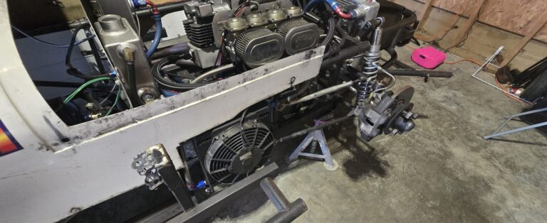
Once 1, 2 and 3 from the image above are removed, go ahead and connect the lower radiator hose directly to the inlet on the block as pictured below.

Circled in red is the lower radiator hose connected directly to the block. Just above the circle is the water pump housing outlet that will direct coolant to the rear of the block. (3a from above). Arrows show coolant flow.
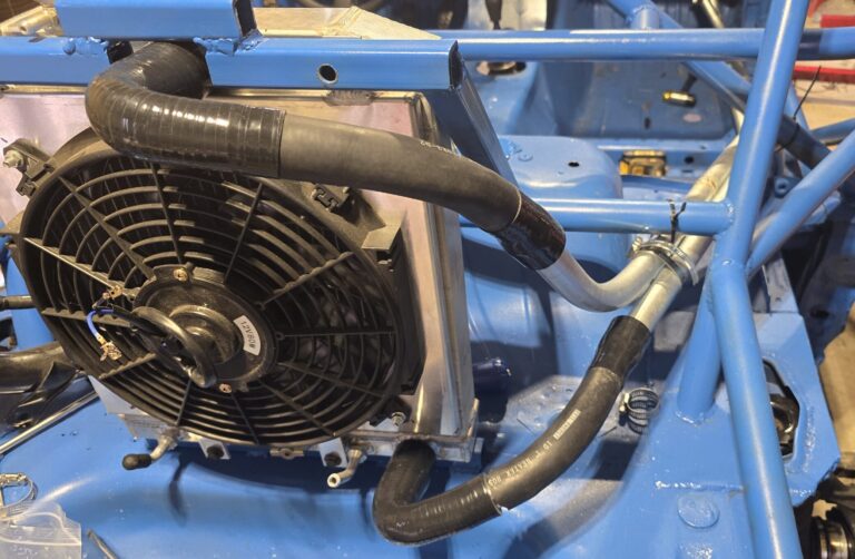
Now a coolant hose must be run from the upper outlet (1a) to the rear of the block (3a). To do this I used 5/8″ high temp heater hose, 1″ heater (for shielding), 2 90 degree 1/2″ copper elbows and a few hose clamps. There is a lot of flexibility for the coolant path but I chose to run by line under the main chamber of the intake manifold in order to support the line. I first constructed the line using the 5/8″ hose and then I cut appropriate lengths of the 1″ hose to shield the 5/8″ hose from abrasion. See images below.

Note how the 5/8″ hose is thread through the 1″ hose to protect it from abrasion.

This image shows how the new coolant line is constructed. Using two copper 90 degree elbows and three segments of heater hose, the coolant can now flow directly from the front of the motor to the inlet at the rear.

Coolant outlet from thermo housing.

This is the 90 degree elbow behind the manifold (near the firewall) that directs the coolant to the block. (3a from images above)

The coolant line runs under the main chamber of the intake manifold.
Finally, the exhaust side of the coolant system where the water re-enters the block after passing through the turbo is plugged with a 1/2″ copper plug.

A copper or brass. 1/2″ plug is used to plug the water inlet on the exhaust side. If you still wish to liquid cool your turbo then you can simple add a t (with a reducer) to the new line on the intake side and then run a line to the turbo.